Views: 0 Author: Site Editor Publish Time: 2026-07-13 Origin: Site
The operational safety, payload capacity, and maintenance overhead of any vehicle fleet or performance build hinge entirely on the architecture of its braking mechanisms. Specifying inadequate braking components or misunderstanding system limitations leads to thermal degradation, accelerated component wear, and severe safety liabilities under heavy loads. This guide provides an engineering-level evaluation of modern Automotive Brake Systems, dissecting actuation methods, friction mechanisms, fluid dynamics, and electronic interventions to support precise specification and maintenance decisions. We examine the physics of deceleration, compare disc and drum configurations, analyze fluid chemistry, and outline the electronic safety protocols governing modern vehicle control.
Disc vs. Drum Trade-offs: Disc brakes offer superior thermal dissipation and fade resistance for front-axle and high-performance applications, while drum brakes remain viable for cost-effective, rear-axle load management and integrated parking solutions.
Actuation Dictates Application: Hydraulic systems dominate passenger and light commercial vehicles, whereas pneumatic (air) systems are mandatory for heavy-duty commercial fleets due to their fail-safe design and infinite fluid supply.
Fluid Selection is Critical: Selecting the correct brake fluid chemistry (glycol-ether vs. silicone-based) and managing hygroscopic properties is vital to avoiding system corrosion and vapor lock.
Electronic Integration is Standard: Anti-Lock Braking Systems (ABS), Electronic Brakeforce Distribution (EBD), and Electronic Parking Brakes (EPB) dictate diagnostic protocols and overall system safety architecture.
EV/Hybrid Complexity: The shift toward Brake-by-Wire and regenerative braking requires evaluating kinetic energy recovery efficiency against the mechanical redundancy needed for catastrophic failure mitigation.
Table of Contents
Evaluating an automotive brake system requires separating the friction mechanism from the actuation method. Conflating how a vehicle stops with how the force is transmitted leads to inaccurate component specification. Understanding these distinct pathways ensures proper maintenance and system upgrades. Mechanics and engineers must isolate the hydraulic or pneumatic delivery lines from the mechanical clamping forces at the wheel hub to diagnose faults accurately.
At its core, braking involves converting kinetic energy into thermal energy. Friction materials, such as brake pads or shoes, react against spinning rotors or drums to generate the necessary friction. This thermal energy must then dissipate rapidly into the surrounding air to prevent component failure. When temperatures exceed the operating range of the friction material, the resins bind the pad compound vaporize, creating a gas boundary layer that causes brake fade.
Auxiliary non-friction systems provide alternative deceleration methods. Electromagnetic retarders, or eddy current brakes, and hydrodynamic retarders are frequently utilized in heavy-duty commercial vehicles. These systems manage continuous downhill deceleration without inducing friction wear on the primary brakes. Regenerative systems in hybrid and electric vehicles utilize motor-generators to convert kinetic energy back into stored electrical energy, reducing reliance on mechanical friction components.
Deceleration Type | Mechanism | Primary Application | Thermal Management |
|---|---|---|---|
Mechanical Friction | Pads/Shoes clamping Rotors/Drums | Standard Passenger & Commercial | Air cooling via vented rotors or finned drums |
Electromagnetic Retarder | Eddy currents resisting driveline rotation | Heavy-Duty Transit & Haulage | Internal cooling fins and ambient airflow |
Hydrodynamic Retarder | Viscous fluid shear in transmission | Class 8 Trucks & Heavy Equipment | Integrated heat exchangers tied to engine cooling |
Regenerative Braking | Motor-generator resistance | EVs and Hybrids | Battery thermal management systems |
Tracing the transmission of driver input reveals distinct actuation pathways across different vehicle types. Mechanical actuation relies on steel cable linkages. While historically primary, this method is now largely relegated to mechanical hand brakes and parking assemblies. Hydraulic actuation utilizes fluid-pressure transmission and remains the standard for passenger vehicles due to its rapid response time and compact packaging.
Pneumatic systems rely on compressed air volume and are standard for commercial fleets. Electronic actuation, or Brake-by-Wire, uses signal-to-actuator control, decoupling the physical pedal from the hydraulic circuit. Each pathway presents unique characteristics regarding latency, force multiplication ratios, and mechanical efficiency.
Mechanical: Direct physical linkage. High effort, low multiplication. Prone to cable stretch and corrosion.
Hydraulic: Incompressible fluid transfer. Excellent pedal feel and immediate response. Requires sealed lines and regular fluid flushes.
Pneumatic: Compressible gas transfer. Slight latency in application. Infinite supply via onboard compressors.
Electronic: Sensor-driven motor actuation. Zero latency. Requires heavy redundancy for safety compliance.
The foundational friction systems utilized at the wheel hub dictate the vehicle's stopping capabilities and maintenance requirements. This section details the primary mechanisms, including integrated parking brake mechanics. The choice between disc and drum architectures heavily influences unsprung weight, thermal capacity, and service intervals.
Disc brake systems utilize calipers to clamp brake pads against a spinning rotor. Calipers can feature floating or fixed multi-piston designs. Floating calipers use a single piston (or dual pistons on one side) and slide on guide pins to pull the outboard pad against the rotor. Fixed calipers mount rigidly to the knuckle and use opposing pistons to squeeze the pads, offering superior clamping force and rigidity for high-performance applications.
This mechanism provides rapid heat dissipation and superior performance in wet conditions, as centrifugal force effectively sheds water from the rotor surface. Rotors are typically cast iron and feature internal cooling vanes (vented rotors) on front axles to pump air from the center hub outward. These systems deliver a linear pedal feel and allow for straightforward visual inspection. Disc brakes are standard on all modern front axles and remain the preferred choice for performance builds, towing applications, and high-duty-cycle environments.
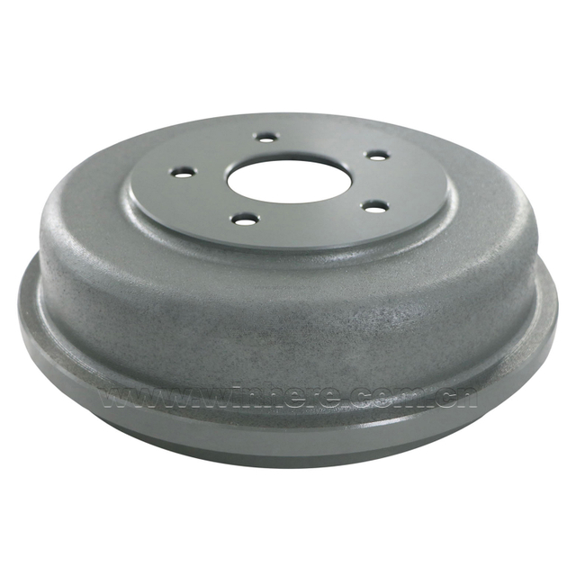
Drum brake systems operate via hydraulic wheel cylinders that push brake shoes outward against the inner surface of a rotating drum. Key design variants include leading-trailing shoe designs and duo-servo configurations. Duo-servo designs leverage rotational force to self-energize, increasing stopping force with minimal pedal effort. As the drum rotates, it drags the primary shoe into the secondary shoe, wedging them both tightly against the friction surface.
Drum brakes offer exceptional self-energizing torque, lower manufacturing costs, and simplified integrated parking brake shoe configurations. However, they are highly susceptible to heat accumulation, leading to rapid brake fade under sustained loads. The enclosed design traps brake dust and heat. Rebuilding drum brake assemblies involves complex mechanical procedures, requiring specialized spring pliers and careful adjustment of the star wheel mechanism to ensure proper shoe-to-drum clearance.
Mechanical hand brakes use cable-operated systems that bypass the primary hydraulic circuit. They mechanically lock the rear wheels by either clamping the rear calipers via a cam mechanism or engaging a drum-in-hat system located inside the hub of a rear disc rotor. This provides a reliable mechanical backup independent of hydraulic pressure.
Electronic Parking Brakes utilize caliper-mounted electric motors acting directly on the caliper piston. These systems frequently integrate with Hill-Start Assist and automated emergency braking protocols, enhancing overall vehicle safety and convenience. Servicing EPB systems requires a diagnostic scan tool to retract the electric motors before the caliper pistons can be compressed for pad replacement.
Assessing how force is generated, multiplied, and delivered to friction components depends heavily on vehicle weight, duty cycle, and operational environment. Understanding these methods is crucial for maintaining optimal braking performance and diagnosing soft pedals, dragging brakes, or complete system failures.
Hydraulic braking relies on Pascal’s Law, utilizing incompressible brake fluid to transfer force from the master cylinder to the wheel cylinders or calipers. The master cylinder converts mechanical pedal travel into hydraulic pressure, splitting the system into two independent circuits (front/rear or diagonal) for safety redundancy. The chemical specification of the brake fluid is critical to system integrity.
Glycol-ether-based fluids, such as DOT 3, DOT 4, and DOT 5.1, are highly hygroscopic, meaning they absorb water over time. Comparing dry versus wet boiling points highlights the risk of vapor lock, where fluid boils under heavy thermal load, introducing compressible gas into the lines. Silicone-based DOT 5 fluid is hydrophobic and non-corrosive to paint, often used in military or classic vehicles. However, it is incompatible with ABS systems due to foaming under rapid cycling. Regular flush intervals mitigate water contamination, internal steel line corrosion, and seal degradation.
Fluid Type | Base Chemistry | Dry Boiling Point (Min) | Wet Boiling Point (Min) | Primary Use Case |
|---|---|---|---|---|
DOT 3 | Glycol-Ether | 401°F (205°C) | 284°F (140°C) | Standard Passenger Vehicles |
DOT 4 | Glycol-Ether/Borate | 446°F (230°C) | 311°F (155°C) | Heavy Duty & Performance |
DOT 5 | Silicone | 500°F (260°C) | 356°F (180°C) | Classic Cars (Non-ABS) |
DOT 5.1 | Glycol-Ether/Borate | 500°F (260°C) | 356°F (180°C) | Severe Duty & Racing |
Pneumatic brake systems utilize compressed air stored in dual reservoirs and are standard in Class 7 and 8 commercial vehicles. These systems feature a fail-safe dual-circuit design utilizing spring brakes. The parking and emergency brakes are held open by positive air pressure acting against a heavy mechanical spring inside the brake chamber.
If air pressure is lost due to a blown line or compressor failure, the heavy-duty springs automatically expand, locking the wheels to prevent catastrophic runaway. Maintaining these systems requires servicing air compressors, governors, air dryers, and automatic slack adjusters. Regular manual draining of air tanks prevents moisture from accumulating and freezing in cold climates, which blocks air valves and causes total system failure.
Vacuum assist systems, or vacuum boosters, utilize engine manifold vacuum or an auxiliary vacuum pump to multiply the pedal force applied to the master cylinder. A diaphragm inside the booster separates atmospheric pressure from engine vacuum. When the pedal is depressed, atmospheric pressure enters one side, pushing the diaphragm and assisting the pushrod into the master cylinder.
Hydro-Boost systems utilize hydraulic pressure from the power steering pump instead of vacuum. These are typically specified for diesel engines, which lack natural manifold vacuum, or for medium-duty commercial applications requiring higher line pressure. Hydro-Boost units contain a spool valve that directs pressurized steering fluid to assist the master cylinder pushrod, providing massive clamping force for heavy vehicles.
Brake-by-Wire technology decouples the physical brake pedal from the hydraulic circuit. It uses pedal travel sensors and high-pressure electric motors to generate hydraulic line pressure. This allows for precise control, seamless blending of regenerative and friction braking in EVs, and integration with advanced driver-assistance systems like adaptive cruise control.
Redundancy requirements are strict for these systems. Mechanical backup hydraulic valves must open in the event of total electrical power loss to preserve emergency braking capability. In a failure state, the driver pushes through a heavy, unassisted pedal to manually generate line pressure, ensuring the vehicle can still be stopped safely.
Modern Automotive Brake Systems rely heavily on electronic overlays to maintain traction, stability, and regulatory compliance. These systems manage complex dynamic forces during deceleration, preventing loss of control during emergency maneuvers.
Anti-Lock Braking Systems prevent wheel lockup during hard braking. Wheel speed sensors monitor rotational speed at each hub, sending data to the electronic control unit (ECU). If the ECU detects rapid deceleration indicating impending lockup, it commands the hydraulic control unit (HCU) to rapidly isolate, dump, and reapply hydraulic pressure to that specific wheel.
This rapid modulation maintains the tire's slip ratio at the optimal peak for traction, allowing the driver to maintain steering control and prevent skidding. ABS significantly reduces stopping distances on slippery surfaces and serves as the foundational architecture for Electronic Stability Control (ESC) and Traction Control Systems (TCS).
Inspect wheel speed sensor wiring harnesses for chafing or debris damage.
Clean magnetic tone rings on CV axles or wheel hubs to ensure accurate sensor readings.
Flush brake fluid regularly to prevent moisture from corroding the internal valves of the ABS HCU.
Use a bidirectional scan tool to bleed the ABS module if air enters the primary hydraulic circuit.
Execute the following steps to ensure your braking systems remain operational and safe under all load conditions.
Flush and replace hydraulic brake fluid every 24 months to eliminate moisture accumulation and prevent internal corrosion.
Measure rotor thickness with a micrometer during every pad replacement to ensure the disc meets minimum safe operating specifications.
Drain pneumatic air tanks daily on commercial vehicles to expel condensation and prevent valve freeze-ups in cold weather.
Retract electronic parking brake calipers using a dedicated diagnostic scan tool before attempting rear brake pad service.
No matter the application, selecting, upgrading, and maintaining your vehicle's braking mechanisms requires a balanced understanding of raw mechanical friction, fluid characteristics, and electronic safety protocols. To guarantee the highest standards of safety, thermal performance, and durability for high-demand passenger and commercial applications, choosing precision-engineered components is essential. As an industry leader in manufacturing high-performance stopping technology, WINHERE excels in casting and machining professional-grade brake discs, premium rotors, and heavy-duty drums tailored for modern hydraulic, pneumatic, and electric configurations. Ensuring your builds utilize robust hardware guarantees continuous operational uptime and uncompromised fleet safety on the road.
A: Brake fade occurs when friction components overheat, exceeding their thermal capacity. This reduces the coefficient of friction between the pad and rotor, requiring increased pedal effort to achieve the same deceleration. Upgrading to high-temperature pads and ensuring proper fluid condition mitigates this issue.
A: No. DOT 3 is glycol-ether-based, while DOT 5 is silicone-based. Mixing them causes severe fluid degradation, seal failure, and compromised braking performance. Always use the specific fluid chemistry recommended by the vehicle manufacturer.
A: Duo-servo drum brake designs utilize the rotational force of the drum to wedge the brake shoes tighter against the friction surface. This mechanical leverage increases stopping force without requiring additional hydraulic pressure from the driver.
A: Brake-by-Wire systems incorporate mechanical redundancy. If electrical power is lost, fail-safe hydraulic valves open, reconnecting the brake pedal directly to the hydraulic circuit, allowing the driver to manually generate line pressure for emergency stops.
A: The air dryer removes moisture and contaminants from the compressed air before it enters the storage reservoirs. This prevents water from accumulating in the lines, which could freeze in cold weather and cause total system failure.