Views: 0 Author: Site Editor Publish Time: 2026-07-13 Origin: Site
The fundamental physics of stopping a moving vehicle remain constant, but the engineering tolerances, material sciences, and electronic integrations defining a modern Vehicle Brake System dictate the line between controlled deceleration and catastrophic failure. Fleet managers, performance builders, and consumers frequently misalign brake component selection with actual operational demands. Misunderstanding the hydraulic and thermal limits of a braking setup inevitably leads to premature component wear, dangerous brake fade under heavy load, and compromised safety compliance.
Evaluating OEM replacements or aftermarket upgrades requires a foundational understanding of how kinetic energy, hydraulic pressure, and friction materials interact in real time. This guide breaks down the mechanics of the system to provide a technical framework for specifying, maintaining, and upgrading brake components based on verifiable performance metrics, ensuring reliable operation under all driving conditions.
Energy Conversion is the Core Mechanic: A vehicle brake system functions by converting kinetic energy into thermal energy via friction; managing this heat dissipation is the primary differentiator between standard and high-performance systems.
Hydraulic Force Multiplication Drives Stopping Power: The master cylinder translates minimal pedal effort—multiplied by mechanical leverage—into thousands of pounds of clamping force, making fluid integrity (boiling point and moisture resistance) a critical failure point.
Material Selection Dictates Performance Outcomes: The choice between organic, semi-metallic, and ceramic friction materials directly impacts stopping distance, rotor longevity, thermal degradation, and noise, vibration, and harshness (NVH) levels.
Electronic Integration is Non-Negotiable: Modern braking relies heavily on Anti-Lock Braking Systems (ABS) and Electronic Stability Control (ESC) to maintain traction, requiring compatible hydraulic and sensor components for safe operation.
Table of Contents
A successful Vehicle Brake System must consistently halt a vehicle's mass without exceeding the thermal limits of its components, losing hydraulic integrity, or exceeding the traction limits of the tires. Understanding the underlying physics is essential for diagnosing performance issues and selecting the right hardware for specific applications.
The core function of any braking mechanism is energy conversion. According to the physics equation of kinetic energy ($KE = \frac{1}{2}mv^2$), the energy a moving object possesses is proportional to its mass and the square of its velocity. This mathematical reality explains why doubling your vehicle speed quadruples the required stopping power and the resulting heat generated. If a vehicle accelerates from 30 mph to 60 mph, the braking components must dissipate four times as much thermal energy to bring the vehicle to a complete stop.
To achieve this, the system relies on a specific friction coefficient between the brake pad and the rotor or drum. The friction material must grip the rotating metal surface firmly enough to slow it down, yet smoothly enough to prevent sudden lockups. However, it is critical to recognize the role of tire traction. The mechanical components slow the rotation of the wheels, but the friction between the tire contact patch and the road surface ultimately stops the vehicle. If the braking force exceeds the tire's grip, the wheel locks, and the vehicle skids, significantly increasing stopping distances and eliminating steering control.
The journey from driver input to vehicle deceleration begins with mechanical leverage. The brake pedal assembly acts as a lever, providing the initial force multiplication before any fluid pressure is generated. By positioning the pivot point strategically, engineers ensure that a relatively light push from the driver's foot is magnified significantly before it even reaches the master cylinder pushrod.
Once this mechanical force enters the hydraulic circuit, Pascal's Principle takes over. This principle states that pressure applied to a confined fluid is transmitted undiminished in every direction throughout the fluid. In practical terms, the small piston inside the master cylinder pressurizes the hydraulic fluid. Because the system is closed, this fluid transmits the pressure equally to the much larger pistons located in the slave cylinders or calipers at each wheel. The difference in surface area between the master cylinder piston and the caliper pistons results in an exponential multiplication of the driver's physical input, generating the thousands of pounds of clamping force necessary to halt a heavy vehicle.
Modern vehicles utilize brake boosters to reduce the physical effort required by the driver. Vacuum boosters harness engine vacuum (or a dedicated vacuum pump) to pull a diaphragm forward when the pedal is depressed, adding significant assist to the driver's input. Hydraulic boosters, often found in heavy-duty trucks, utilize pressure from the power steering pump to achieve the same goal.
This assisted force is directed into the mechanical interface where the pedal pushrod depresses the primary and secondary pistons within the master cylinder. The master cylinder is the heart of the hydraulic network. Modern designs employ a dual-circuit architecture as a critical fail-safe mechanism. By splitting the hydraulic control into two separate circuits—often diagonally (front-left with rear-right) or front-to-rear—engineers ensure that a catastrophic leak in one circuit does not cause complete hydraulic failure. The driver will experience a longer pedal travel and reduced stopping power, but the vehicle will still retain braking capability on at least two wheels.
Hydraulic fluid travels a complex path from the master cylinder reservoir to the wheels. It flows through rigid, thin-walled steel lines running along the vehicle chassis. Near the wheels, where suspension movement and steering articulation occur, the system transitions to flexible rubber hoses.
The fluid itself is highly engineered. Brake fluid classifications, such as DOT 3, DOT 4, and DOT 5.1, are categorized primarily by their dry and wet boiling points. A high boiling point is critical because the friction generated at the wheels transfers immense heat into the calipers. If the fluid boils, it turns into a compressible gas, resulting in a spongy pedal and a total loss of hydraulic force.
Master Cylinder Pressurization: Fluid is pushed from the reservoir into the primary lines.
Proportioning Valve Regulation: Pressure is adjusted to prevent rear-wheel lockup.
Rigid Line Transit: Fluid travels along the chassis via steel lines.
Flexible Hose Articulation: Fluid passes through rubber or braided hoses to accommodate suspension travel.
Caliper Actuation: Fluid enters the slave cylinder, pushing the piston against the brake pad.
While OEM rubber brake hoses are standard, they are prone to volumetric expansion under extreme pressure, which can make the pedal feel soft during aggressive driving. Upgrading to braided stainless steel lines restricts this expansion, providing improved pedal feel and faster system responsiveness. Additionally, proportioning valves and distribution blocks manage fluid flow, actively reducing pressure to the rear wheels during heavy stops to prevent premature rear-wheel lockup as the vehicle's weight transfers forward.
At the execution phase, the hydraulic pressure is converted back into mechanical friction.
Disc setups utilize calipers, brake pads, and rotors. Calipers can be floating (sliding on pins with pistons on one side) or fixed (rigidly mounted with pistons on both sides). The caliper pistons act as slave cylinders, pushing the friction pads directly against the rotating cast-iron disc. Disc brakes offer superior thermal dissipation because the rotor is exposed to ambient airflow. They also provide excellent wet-weather performance, as the spinning rotor quickly sheds water and debris.
Drum setups utilize wheel cylinders, brake shoes, and heavy iron drums. The wheel cylinder acts as a dual-piston slave cylinder, pushing the curved brake shoes outward against the inside of the spinning drum. While largely replaced by disc brakes on front axles, drum brakes see continued use on rear axles for cost efficiency and the simplicity of integrating a mechanical parking brake. However, their enclosed design makes them highly susceptible to heat retention, leading to faster brake fade under continuous load.
Matching friction materials and rotor designs to specific vehicle applications—whether for daily commuting, heavy towing, or track use—is critical for optimizing the Vehicle Brake System.
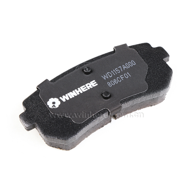
The composition of the brake pad dictates stopping distance, operating temperature range, and rotor wear.
Material Type | Characteristics | Best Application |
|---|---|---|
Organic (NAO) | Low noise, low rotor wear, generates minimal dust. Poor high-temperature stability. | Light daily driving and standard passenger commuting. |
Semi-Metallic | Excellent heat dissipation, high friction coefficient. High rotor wear, increased brake dust, and potential for noise. | Heavy towing, fleet vehicles, and performance track use. |
Ceramic | Consistent performance, very low dust, quiet operation. Higher upfront cost, lower cold-bite performance. | Premium passenger vehicles and luxury daily drivers. |
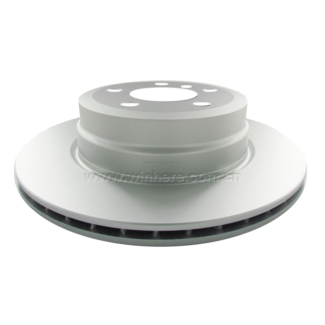
Rotors act as the primary heat sink for the entire system. Blank rotors offer the maximum surface area and structural integrity, making them the standard choice for most applications. Slotted rotors feature machined grooves that help wipe the pad surface clean, preventing pad glazing and allowing hot gases to escape during heavy use. Drilled rotors provide weight reduction and improved wet weather bite by giving water an escape route. However, drilled rotors are prone to micro-cracking between the holes under extreme thermal cycling, making them less ideal for dedicated track vehicles despite their aggressive appearance.
Modern software and sensor integrations have fundamentally enhanced the mechanical foundation, turning passive hydraulics into active safety networks.
ABS utilizes wheel speed sensors at each corner to monitor rotational velocity. If a sensor detects a wheel decelerating too rapidly—indicating an impending lockup—the ABS hydraulic control unit rapidly modulates pressure to that specific slave cylinder. By pulsing the brakes faster than a human foot ever could, ABS allows the driver to maintain steering control during panic stops. Building upon this, ESC applies asymmetric braking to individual wheels to correct understeer or oversteer, keeping the vehicle on its intended path during evasive maneuvers.
EBD dynamically adjusts hydraulic pressure between the front and rear axles based on vehicle load distribution and weight transfer. If the trunk is heavily loaded, EBD sends more pressure to the rear brakes than it would if the vehicle were empty, optimizing stopping power. Brake Assist systems monitor the speed and force of the driver's pedal application. If the system detects a panic braking scenario, it instantly maximizes hydraulic pressure to engage ABS fully, compensating for drivers who fail to press the pedal hard enough during an emergency.
Electric vehicles and hybrids introduce regenerative braking, fundamentally altering maintenance schedules. When the driver lifts off the accelerator, the electric traction motors reverse polarity, acting as generators. This process captures kinetic energy, converts it back into electricity to recharge the battery, and simultaneously slows the vehicle. This magnetic resistance significantly reduces the mechanical load on the traditional friction brake system, allowing pads and rotors to last tens of thousands of miles longer than their internal combustion counterparts.
Identifying the root causes of system degradation and establishing proactive maintenance protocols is essential for long-term safety.
Brake fade is the terrifying loss of stopping power during sustained use, typically occurring in two distinct forms. Fluid fade is caused by hygroscopic brake fluid absorbing moisture from the atmosphere over time. This moisture drastically lowers the fluid's boiling point. Under heavy braking, the fluid boils, creating compressible steam pockets in the lines, resulting in a spongy pedal that goes straight to the floor. Pad fade, conversely, occurs when friction materials exceed their thermal limits. The overheated resins in the pad begin to off-gas, creating a frictionless boundary layer of gas between the pad and rotor. The driver will feel a rock-hard pedal, but the vehicle will not decelerate.
Sourcing replacement parts requires strict attention to quality. Cheap aftermarket components often utilize inferior metallurgy and inconsistent friction compounds, leading to premature rotor warping, increased NVH (noise, vibration, and harshness), and extended stopping distances. It is imperative to verify ECE R90 or DOT compliance when purchasing replacement parts. These certifications ensure the components meet stringent OEM-level safety and performance benchmarks, mitigating the hidden costs and safety risks associated with substandard hardware.
To safely navigate heavy payloads, rapid thermal cycles, and demanding environments, matching your hardware architecture to the vehicle's specific operating profile remains essential. Achieving exceptional dependability on the road requires partnering with verified manufacturing leaders who construct components under stringent global standards. As an international manufacturing powerhouse specializing in high-performance stopping technology, WINHERE excels in casting and machining professional-grade brake discs, heavy-duty drums, and premium rotors optimized for complex hydraulic and electronic safety networks. Relying on precision-engineered components guarantees maximum fleet uptime, robust fade resistance, and uncompromised control under all driving conditions.
Inspect current pad thickness and rotor runout using a micrometer to establish a baseline for component wear.
Test brake fluid moisture content with a digital tester and schedule a full system flush if moisture exceeds 3%.
Verify compatibility of any planned friction compound upgrades with your vehicle's factory ABS and ESC modules.
Consult OEM technical specifications to ensure replacement rotors meet the required metallurgical standards for your specific gross vehicle weight.
A: When brake fluid boils, it turns from an incompressible liquid into a compressible gas. When the driver presses the brake pedal, the hydraulic force compresses the gas bubbles instead of clamping the brake pads, resulting in a spongy pedal and a severe loss of stopping power.
A: Disc brakes are exposed to open air, allowing them to dissipate heat much faster than enclosed drum brakes. This superior cooling prevents brake fade during heavy use. Additionally, the spinning rotor easily sheds water and debris, maintaining consistent friction in wet conditions.
A: Pad fade occurs when overheated friction material off-gasses, creating a slippery barrier between the pad and rotor, resulting in a hard pedal but no stopping power. Fluid fade happens when brake fluid boils into a gas, causing a soft, spongy pedal that fails to transmit hydraulic force.
A: Regenerative braking uses the vehicle's electric motors to slow the car down by converting kinetic energy into electrical energy. Because the motors handle most of the deceleration, the mechanical friction brakes are used far less frequently, drastically extending the lifespan of the brake pads and rotors.
A: For standard daily driving, blank rotors are usually the best choice as they offer maximum surface area and durability. While drilled and slotted rotors help clear gases and water, they are generally unnecessary for commuting and can increase pad wear and noise.
A: The master cylinder converts the mechanical force from the driver's foot on the brake pedal into hydraulic pressure. It forces brake fluid through the brake lines to the slave cylinders at each wheel, multiplying the force required to clamp the friction materials.
A: Brake fluid is hygroscopic and absorbs moisture over time. It should typically be flushed and replaced every two years or 24,000 miles, depending on the manufacturer's specifications, to prevent fluid boil and internal corrosion.